Mission Planner CLI Setup Test modes
Command Line Interpreter
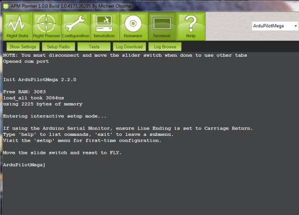
The Mission Planner Command Line interpreter is a serial terminal line editor that works similarly to the way the old DOS prompt operating systems used to work. If you want, you can set up and test APM is via a Command Line Interpreter (CLI). It is only available via the USB cable and it cannot be used via an Xbee or 3DR wireless telemetry connection. Open up the Terminal in the Mission Planner by selecting the Terminal tab (ensure that the serial baud rate is set for 115200). This will bring up the Terminal window, and it should automatically take you to the APM CLI menu (if not, click in the window and hit “Enter” three times):
You can now enter commands by typing them at the command prompt. You can always type “exit” to leave any mode. In the following examples, I’ll be using another serial terminal (in this case the Arduino Serial Monitor). You can use any terminal you want, but the Mission Planner terminal is the most straightforward. Here I’m typing “help” to see a list of available commands:
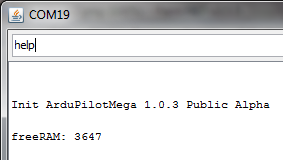
Initial commands are:
logs: Log readback/setup mode. Used after flying)
setup: Initial setup mode)
test: Test mode)
Setup
The Setup process configures APM for your particular RC radio settings and desired flight modes. Type “setup” and hit return to enter this mode. You MUST setup both radio and modes before you can fly. You should also test that you’re getting GPS lock (using the gps command in the test mode), which usually means testing outside where the GPS module has a clear view of the sky. Allowed setup commands are:
reset: Resets APM to default settings
radio: Sets up RC settings (see below)
modes: Sets up flight control modes for each RC toggle switch position (see below)
compass: Enables compass. Commands are “compass on” or “compass off”
declination: Sets local magnetic declination for compass. You can find your local declination at this web page. Although it is given in minutes and seconds, enter it as a decimal. So
14° 10' Ewould be entered as 14.10.“battery”: Enables battery monitoring. Enter options 0-4 (repeat to enter additional options):
0 = Batt monitoring disabled
1 = Monitoring 3 cell battery
2 = Monitoring 4 cell battery
3 = Monitoring batt volts
4 = Monitoring both volts and current
“show”: Shows all current settings in EEPROM
“erase”: Erases EEPROM
Radio setup
Note: APM does not power the RC receiver or servos (although the RC equipment can power APM). If you have APM powered by USB, you must also connect an ESC/Lipo or receiver battery to the RC APM pins (typically, the ESC would be plugged into Out 3, while a receiver battery would typically be plugged into your receiver, which would send power to APM via the RC cables). If you do not separately power the RC system, APM will be unable to read any signals on its RC inputs. In this mode you must move both sticks to all of their extremes, as follows: Move the right stick to the top right, then bottom right, then top left, then bottom left. Then repeat for the left stick. The order doesn’t matter, but what’s important is that you hit all four corners for each stick. Hold the stick in each corner for a second. Here’s a screenshot of a typical Radio setup process:
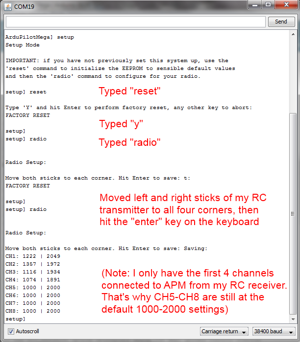
Note: As shown above, the RC readings for the channels you have hooked up should be around 1,000-1,300 at the low end and around 1,900-2,000 at the high end. (Readings of exactly 1,000 and 2,000 mean that channel’s not connected at all). If you are getting readings that are all around 1,500, there are three likely causes:
You didn’t move both sticks to all four corners of their range during the test, or did it too quickly.
Your RC connections are plugged in wrong, either upside down, on the wrong pins, or otherwise not making a connection
Flight Control Modes
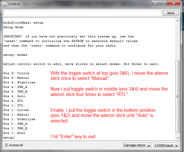
Here’s how to set your flight control modes: In the CLI, enter setup mode. Type “modes” and press return. You can now see the flight modes displayed as you move your control switch to each position. If you want to change your mode, use the rudder/aileron control stick on your radio. Just move the stick to the right or left and the mode will increment. Hitting Enter will exit the mode and save your changes. See this example:
Here’s a video tutorial:
Checking for reversed servos
Now is a good time to go back and see if any of the DIP switches need to be flip to reverse a servo. Instructions are here. And remember that if you’re flying an elevon plane (flying wing or delta), you should set the mixing with the DIP switch, too. And if you’re flying a regular plane and find that channel 1 and 2 are accidentally combined, that means you’ve accidentally got it in the elevon mode. Push the last DIP switch down to return to normal.
Logs
This mode allows you to read and manage flight log files in the onboard 16MB dataflash memory. NOTE: You must use erase before trying to use the logging function. Failure to do an erase first will cause problems and show false results.
“dump (n)”: Dump log “n”
“erase”: Erase all logs
“enable (name) or all”: Enable logging “name” or everything
“disable (name) or all”: Disable logging “name” or everything
CLI APM Test Suite
APM comes with a number of onboard tests. To use them, type “test” in the CLI, and “help” to see all the different tests:
baro: Shows the data from the barometer
compass: Shows the data from the magnetometer, if one is connected and enabled
ins: tests the accelerometers and gyros
optflow: Tests optical flow sensor
relay: Tests the onboard relay (turns it on and off every five seconds; you should hear it faintly click)
shell: Provides access to the NSH shell (Pixhawk only)
rangefinder: Tests the rangefinder sensor