EKF2 Estimation System
What is the EKF2 Estimation System?
It is a 24 state extended Kalman filter in the AP_NavEKF2 library that estimates the following states
Attitude (Quaternions)
Velocity (North,East,Down)
Position (North,East,Down)
Gyro bias offsets (X,Y,Z)
Gyro scale factors (X,Y,Z)
Z accel bias
Earth magnetic field (North,East,Down)
Body magnetic field (X,Y,Z)
Wind Velocity (North,East)
It is based on the filter equations derived here.
EKF2 Advantages
It can run a separate EKF2 for each IMU making recovery from an IMU fault much more likely
It can switch between magnetometers if there is fault
It can estimate gyro scale factors which can improve accuracy during high rate manoeuvres.
It can simultaneously estimate both gyro offsets and orientation on startup whilst moving and doesn’t rely on the DCM algorithm for its initial orientation. This makes it ideal for flying from moving platforms when the gyro has not been calibrated.
It can handle larger gyro bias changes in flight
It is able to recover faster from bad sensor data
It provides a slightly smoother output.
It is slightly more accurate
It uses slightly less computing power
It starts using GPS when checks pass rather than waiting for the vehicle motors to arm.
How does it achieve this?
Instead of trying to estimate the quaternion orientation directly, it estimates an error rotation vector and applies the correction to the quaternion from the inertial navigation equations. This is better when there are large angle errors as it avoids errors associated with linearising quaternions across large angle changes.
See “Rotation Vector in Attitude Estimation”, Mark E. Pittelkau, Journal of Guidance, Control, and Dynamics, 2003” for details on this approach.
The new EKF runs on a delayed time horizon so that when measurements are fused, they are done so using the measurement, filter states and covariance matrix from the same point in time. The legacy EKF uses a simpler method where delayed measurements are fused using delayed states but the covariance matrix is from the current time which reduces accuracy.
The delayed filter states are then predicted forward into the current time horizon using a complementary filter that removes the time delay and also filters out the sudden changes in the states that occur when measurements are fused.
This approach was inspired by the output predictor work done by Ali Khosravian from ANU. “Recursive Attitude Estimation in the Presence of Multi-rate and Multi-delay Vector Measurements,” A Khosravian, J Trumpf, R Mahony, T Hamel - American Control Conference, vol.-, 2015.
This is computationally much cheaper than winding the states forward using buffered IMU data at each update, but slightly less accurate. The legacy EKF smooths the state corrections by applying them incrementally across the time to the next measurement which reduces stability of the filter.
Further optimisation of mathematics and code to improve speed have been introduced.
A simple compass yaw angle fusion method with fixed declination has been added which is used on the ground or when magnetic interference prevents use of the more accurate 3-axis 6-state magnetometer fusion technique.
Using EKF2
Enable the new EKF by setting EK2_ENABLE = 1. EKF2 will now be running in parallel and logging, etc but it will not be used by the control loops.
To use it in the control loops, set AHRS_EKF_TYPE = 2
The use of multiple IMU’s, is controlled by the EK2_IMU_MASK parameter:
To use only IMU1, set EK2_IMU_MASK = 1 (this is the default)
To use only IMU2, set EK2_IMU_MASK = 2
To run dual EKF2 using IMU1 and IMU2, set EK2_IMU_MASK = 3
After setting the parameters you will need to reboot.
EKF2 Log Data
The data for EKF2 can be found in the NKF1 to NKF5 log packets.
Packets NKF1 to NKF4 contain information for each EKF instance with the instance number given by the value of field PI. The number of instances enabled is set by the EK2_IMU_MASK parameter. Packet NKF5 contains optical flow information for the EKF instance that is the primary for flight control.
The available EKF2 log data is listed below. Some plots showing example flight data have been included. This data was logged using a Pixhawk on a 3DR Iris+ quadcopter with the following parameter changes followed by a reboot:
EK2_ENABLE = 1 (turns on EKF2)
EK2_IMU_MASK = 3 (Instructs EKF2 to run two instances, one for IMU1 (MPU6000) and one for IMU2 (LDG20H + LSM303D)
AHRS_EKF_TYPE = 2 (tells the flight control system to use EKF2
LOG_BITMASK = 131071 (logs 50Hz data from startup)
*Note: Plots can be viewed in full size by left clicking them*
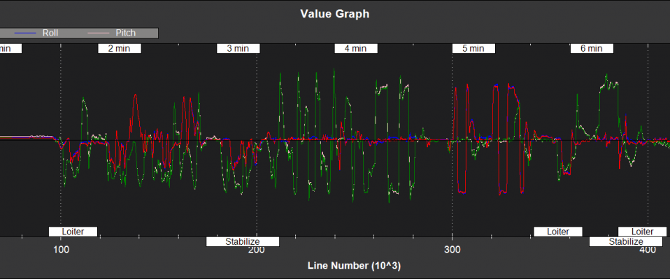
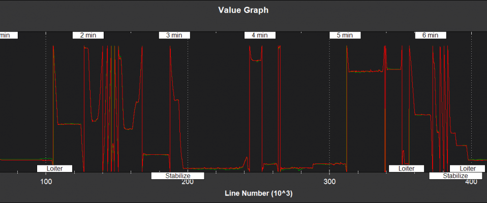
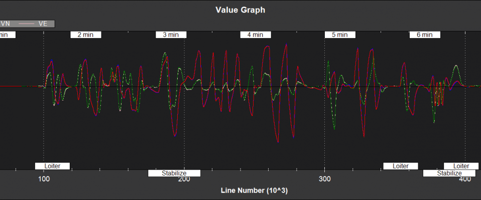
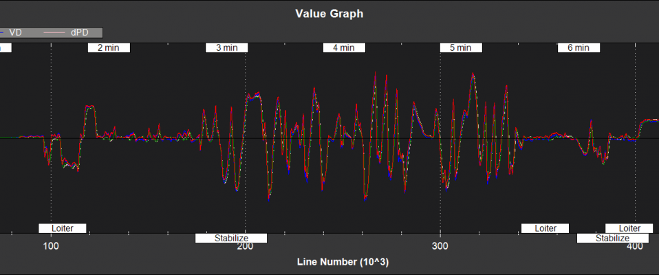
Filter State Estimates
NKF1[0] (and NKF1[1] if a second IMU is being used) contain the outputs used by the flight control system
TimeUS - time stamp (uSec)
Roll,Pitch - Euler roll and pitch angle (deg)
Yaw - Euler yaw angle (deg)
VN,VE - Velocity North,East direction (m/s)
VD, dPD - Velocity and Position Derivative Down (m/s)
PN,PE,PD - Position North,East,Down (m)
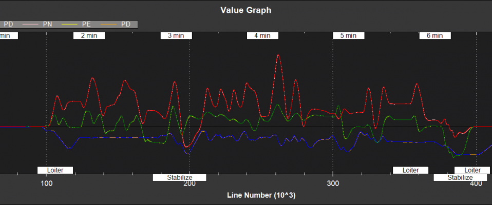
GX,GY,GZ - X,Y,Z rate gyro bias (deg/sec)
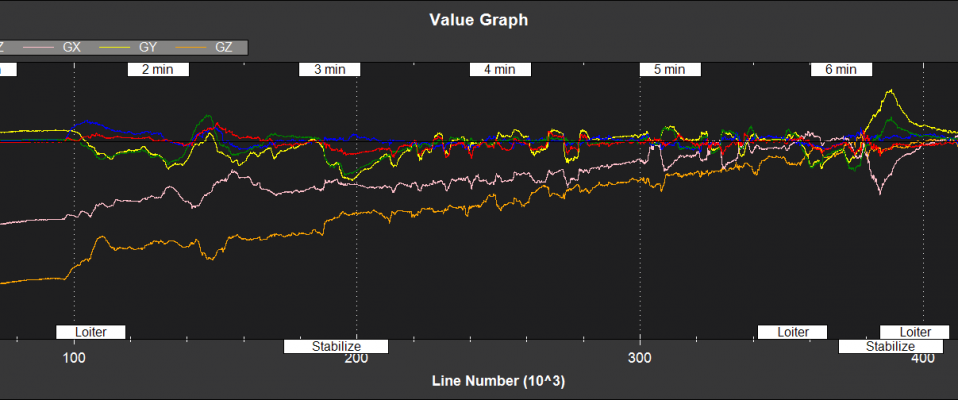
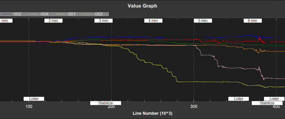
NKF2[0] (and NKF2[1] if a second IMU is being used) contains additional state information
TimeUS - time stamp (uSec)
AZbias - Z accelerometer bias (cm/s/s)
GSX,GSY,GSZ - X,Y,Z rate gyro scale factor (%)
Eg, a log value of 0.5 would be equivalent to a scale factor of 1.005 for that sensor
VWN,VWE - Wind velocity North,East (m/s)
MN,ME,MD - Earth magnetic field North,East,Down (mGauss)
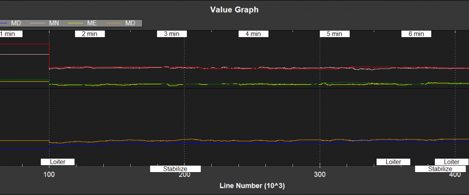
MX,MY,MZ - Body fixed magnetic field X,Y,Z (mGauss)
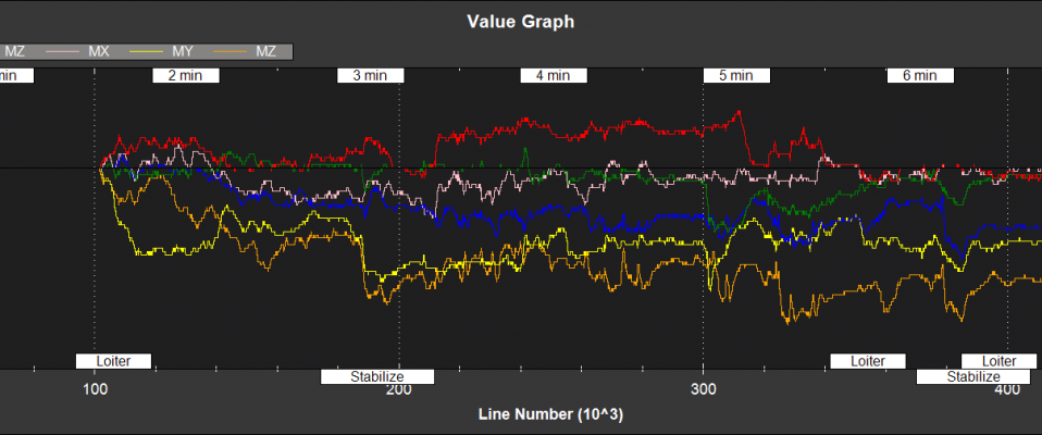
MI - Index of the magnetometer being used by EKF2
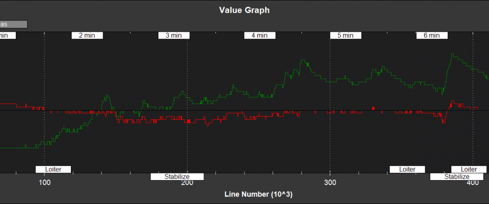
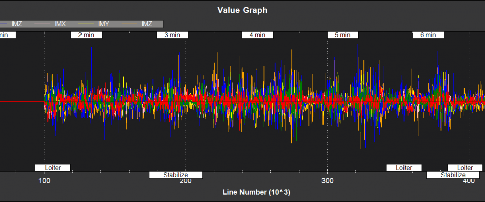
Filter Innovations
NKF3[0] (and NKF3[1] if a second IMU is being used) contain information on the filter innovations. An innovation is the difference between the measurement value predicted byEKF2 and the value returned by the sensor. Smaller innovations indicate smaller sensor errors. Because the IMU data is used to do the prediction, bad IMU data can result in large innovations for all measurements.
TimeUS - time stamp (uSec)
IVN,IVE - GPS velocity innovations North, East (m/s)
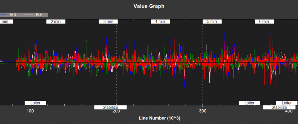
IVD - GPS velocity innovation Down (m/s)
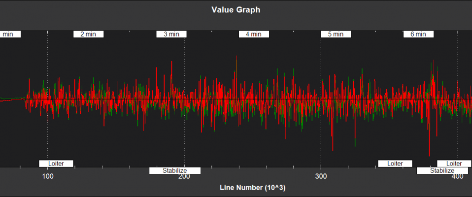
IPN,IPE - GPS position innovations North,East (m)
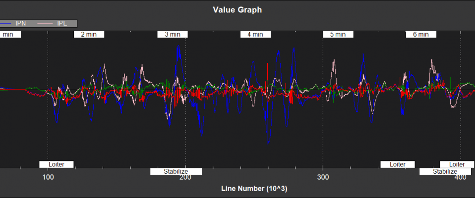
IPD - Barometer position innovation Down (m)

IMX,IMY,IMZ - Magnetometer innovations X,Y,Z (mGauss)
IYAW - Compass yaw innovation (deg)
IVT - True airspeed innovation (m/s)
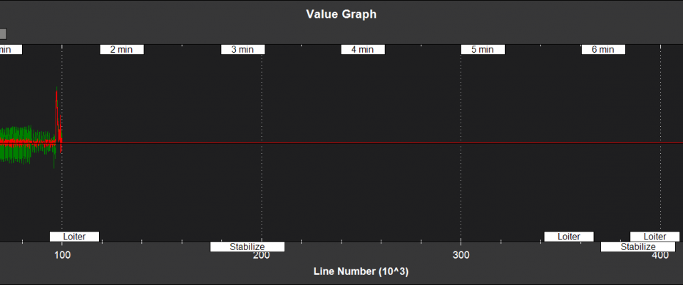
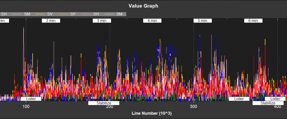
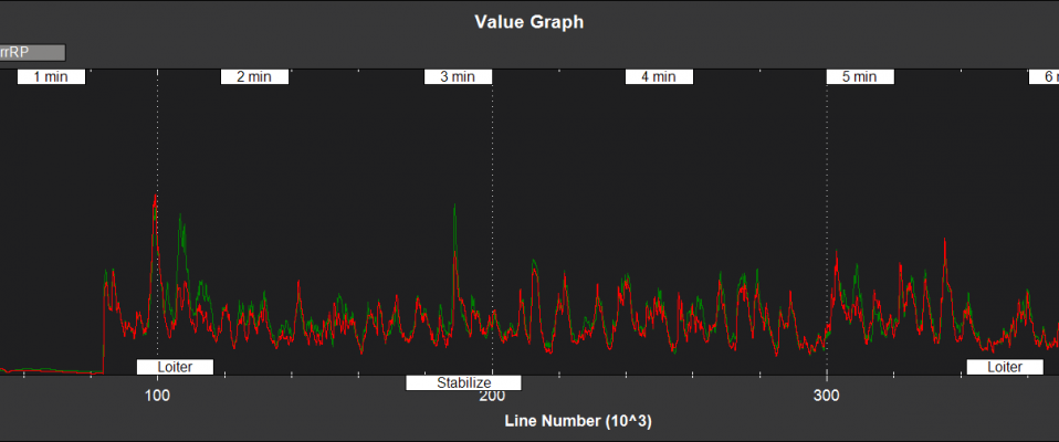
Filter Health and Status
NKF4[0] (and NKF4[1] if a second IMU is being used) contain information on the innovation variance test ratios. A value of less than 1 indicates that that measurement has passed its checks and is being used by the EKF2. A value of more than 1 indicates that the innovations for that measurement are so high that the EKF2 will be rejecting the data from that sensor. Values of less than 0.3 in flight are typical for a setup with good quality sensor data.
They also contain other information relevant to filter health
TimeUS - time stamp (uSec)
SV - GPS velocity test ratio
SP - GPS position test ratio
SH - Barometer test ratio
SM - Magnetometer test ratio
SVT - Airspeed sensor Test ratio
errRP - Estimated attitude roll/pitch error (rad)
OFN - Position jump North due to the last reset of the filter states (m)
OFE - Position jump East due to the last reset of the filter states (m)
FS - Integer bitmask of filter numerical faults
TS - Integer bitmask of filter measurement timeout
SS - Integer bitmask of filer solution status
GPS - Integer bitmask of filter GPS quality checks
PI - Index showing which instance of EKF2 has been selected for flight control
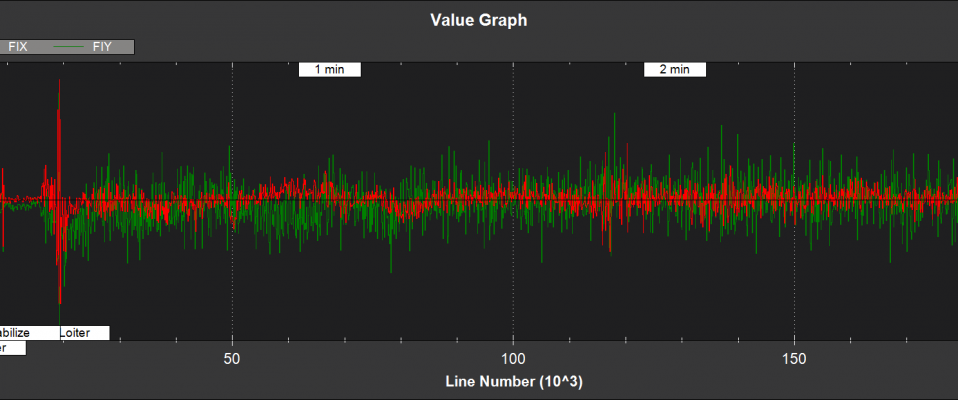
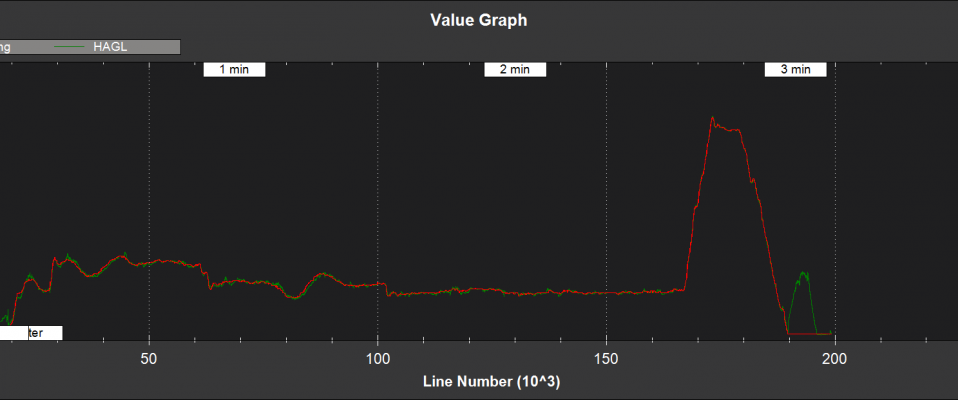
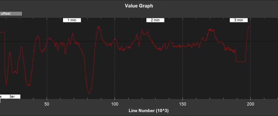
Optical Flow and Range Finder Fusion
NKF5 contains information on the optical flow fusion for the EK2 instance bing used for flight control
TimeUS - time stamp (uSec)
normInnov - optical flow innovation variance test ratio
FIX,FIY - optical flow X and Y axis innovations (mrad/s)
AFI - optical flow terrain height estimator innovation (mrad/s)
HAGL - estimated height above ground level (m)
meaRng - Range measured by the range finder (m)
offset - estimated terrain offset relative to the pressure height origin
RI - Range finder innovation (m)

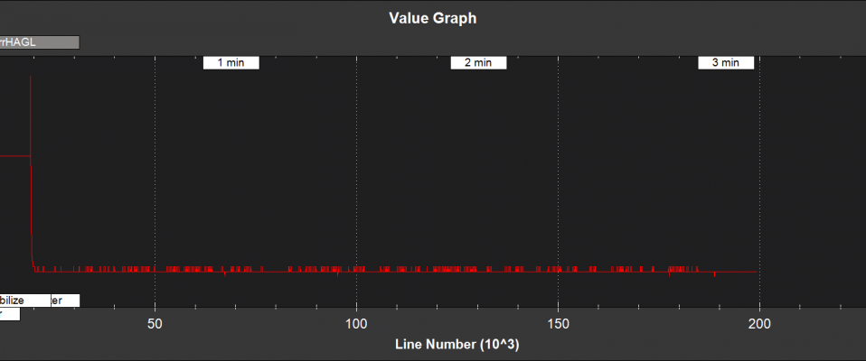
errHAGL - 1-Sigma uncertainty in the terrain height offset estimate (m)
Tuning Parameters
The EKF2 parameters have been tuned to provide a compromise between accuracy and robustness to sensor errors. it is likely that further improvements in performance are available with further tuning.
If you have a question regarding tuning of the filer, please post on the forums along with your log file and mention the term EKF2 in your post title.
The parameters for the new EKF start with the prefix EK2_ and are listed below
EK2_ENABLE
This turns the EKF 2 on and off. Set to 1 to turn on and 0 to turn off. Turning EKF2 on only makes the calculations run, it does not mean it will be used for flight control. To use it for flight control set AHRS_EKF_TYPE=2. A reboot or restart will need to be performed after changing the value of EK2_ENABLE for it to take effect.
EK2_GPS_TYPE
This controls the use of GPS measurements :
0 = use 3D velocity & 2D position
1 = use 2D velocity and 2D position
2 = use 2D position
3 = use no GPS (optical flow will be used if available)
EK2_VELNE_NOISE
This sets a lower limit on the speed accuracy reported by the GPS receiver that is used to set horizontal velocity observation noise. If the model of receiver used does not provide a speed accuracy estimate, then the parameter value will be used. Increasing it reduces the weighting of the GPS horizontal velocity measurements. It has units of metres/sec
EK2_VELD_NOISE
This sets a lower limit on the speed accuracy reported by the GPS receiver that is used to set verical velocity observation noise in. If the model of receiver used does not provide a speed accuracy estimate, then the parameter value will be used. Increasing it reduces the weighting of the GPS vertical velocity measurements. It has units of metres/sec.
EK2_VEL_GATE
This sets the number of standard deviations applied to the GPS velocity measurement innovation consistency check. Decreasing it makes it more likely that good measurements will be rejected. Increasing it makes it more likely that bad measurements will be accepted.
EK2_POSNE_NOISE
This sets the GPS horizontal position observation noise. Increasing it reduces the weighting of GPS horizontal position measurements. It has units of metres
EK2_POS_GATE
This sets the number of standard deviations applied to the GPS position measurement innovation consistency check. Decreasing it makes it more likely that good measurements will be rejected. Increasing it makes it more likely that bad measurements will be accepted.
EK2_GLITCH_RAD
This controls the maximum radial uncertainty in position between the value predicted by the filter and the value measured by the GPS before the filter position and velocity states are reset to the GPS. Making this value larger allows the filter to ignore larger GPS glitches but also means that non-GPS errors such as IMU and compass can create a larger error in position before the filter is forced back to the GPS position. It has units of metres.
EK2_GPS_DELAY
This is the number of msec that the GPS measurements lag behind the inertial measurements. The maximum delay that can be compensated by the filter is 250 msec.
EK2_ALT_SOURCE
This parameter controls which height sensor is used by the EKF. If the selected option cannot be used, it will default to Baro as the primary height source. Setting 0 will use the baro altitude at all times. Setting 1 uses the range finder and is only available in combination with optical flow navigation (EK2_GPS_TYPE = 3). Setting 2 uses GPS. When height sources other than Baro are in use, the offset between the Baro height and EKF height estimate is continually updated. If a switch to Baro height needs to be made when the filter is operating, then the Baro height is corrected for the learned offset to prevent a sudden step in height estimate.
EK2_ALT_NOISE
This is the RMS value of noise in the altitude measurement. Increasing it reduces the weighting of the baro measurement and will make the filter respond more slowly to baro measurement errors, but will make it more sensitive to GPS and accelerometer errors. It has units of metres.
EK2_HGT_I_GATE
This sets the number of standard deviations applied to the height measurement innovation consistency check. Decreasing it makes it more likely that good measurements will be rejected. Increasing it makes it more likely that bad measurements will be accepted.
EK2_HGT_DELAY
This is the number of msec that the height measurements lag behind the inertial measurements. The maximum delay that can be compensated by the filter is 250 msec.
EK2_MAG_NOISE
This is the RMS value of noise in magnetometer measurements. Increasing it reduces the weighting on these measurements. It has units of mGauss.
EK2_MAG_CAL
This determines when the filter will use the 3-axis magnetometer fusion model that estimates both earth and body fixed magnetic field states. This model is only suitable for use when the external magnetic field environment is stable.
EKF_MAG_CAL = 0 enables calibration when airborne and is the default setting for Plane users.
EKF_MAG_CAL = 1 enables calibration when manoeuvreing.
EKF_MAG_CAL = 2 prevents magnetometer calibration regardless of flight condition, is recommended if the external magnetic field is varying and is the default for rovers.
EKF_MAG_CAL = 3 enables calibration when the first in-air field and yaw reset has completed and is the default for copters.
EKF_MAG_CAL = 4 enables calibration all the time.
EK2_MAG_GATE
This parameter sets the number of standard deviations applied to the magnetometer measurement innovation consistency check. Decreasing it makes it more likely that good measurements will be rejected. Increasing it makes it more likely that bad measurements will be accepted.
EK2_EAS_NOISE
This is the RMS value of noise in equivalent airspeed measurements used by planes. Increasing it reduces the weighting of airspeed measurements and will make wind speed estimates less noisy and slower to converge. Increasing also increases navigation errors when dead-reckoning without GPS measurements. It has units of metres/sec.
EK2_EAS_GATE
This sets the number of standard deviations applied to the airspeed measurement innovation consistency check. Decreasing it makes it more likely that good measurements will be rejected. Increasing it makes it more likely that bad measurements will be accepted.
EK2_RNG_NOISE
This is the RMS value of noise in the range finder measurement. Increasing it reduces the weighting on this measurement. It has units of metres.
EK2_RNG_GATE
This sets the number of standard deviations applied to the range finder innovation consistency check. Decreasing it makes it more likely that good measurements will be rejected. Increasing it makes it more likely that bad measurements will be accepted.
EK2_MAX_FLOW
This parameter sets the magnitude maximum optical flow rate in that will be accepted by the filter. It has units of rad/sec.
EK2_FLOW_NOISE
This is the RMS value of noise and errors in optical flow measurements. Increasing it reduces the weighting on these measurements. It has units of rad/sec.
EK2_FLOW_GATE
This sets the number of standard deviations applied to the optical flow innovation consistency check. Decreasing it makes it more likely that good measurements will be rejected. Increasing it makes it more likely that bad measurements will be accepted.
EK2_FLOW_DELAY
This is the number of msec that the optical flow measurements lag behind the inertial measurements. It is the time from the end of the optical flow averaging period and does not include the time delay due to the 100msec of averaging within the flow sensor.
EK2_GYRO_PNOISE
This control disturbance noise controls the growth of estimated error due to gyro measurement errors excluding bias. Increasing it makes the filter trust the gyro measurements less and other measurements more. It has units of rad/sec.
EK2_ACC_PNOISE
This control disturbance noise controls the growth of estimated error due to accelerometer measurement errors excluding bias. Increasing it makes the filter trust the accelerometer measurements less and other measurements more. It has units of metres/sec/sec.
EK2_GBIAS_PNOISE
This state process noise controls the growth of the gyro delta angle bias state error estimates. Increasing it makes rate gyro bias estimation faster and noisier. It has units of rad/sec.
EKF2_GSCL_PNOISE
This state process noise controls the rate of gyro scale factor learning. Increasing it makes rate gyro scale factor estimation faster and noisier.
EK2_ABIAS_PNOISE
This state process noise controls the growth of the vertical accelerometer delta velocity bias state error estimate. Increasing it makes accelerometer bias estimation faster and noisier. It has units of metres/sec/sec.
EK2_MAG_PNOISE
This state process noise controls the growth of magnetic field state error estimates. Increasing it makes magnetic field bias estimation faster and noisier. It has units of Gauss/sec.
EK2_WIND_PNOISE
This state process noise controls the growth of wind state error estimates. Increasing it makes wind estimation faster and noisier. It has units of metres/sec/sec
EK2_WIND_PSCALE
This controls how much the process noise on the wind states is increased when gaining or losing altitude to take into account changes in wind speed and direction with altitude. Increasing this parameter increases how rapidly the wind states adapt when changing altitude, but does make wind velocity estimates noisier.
EK2_GPS_CHECK
This is a 1 byte bitmap controlling which GPS preflight checks are performed. Set to 0 to bypass all checks. Set to 255 perform all checks. Set to 3 to check just the number of satellites and HDoP. Set to 31 for the most rigorous checks that will still allow checks to pass when the copter is moving, eg launch from a boat. Setting a 1 in the following bit locations causes the corresponding checks to be performed.
0: The receivers reported number of satellites must be >= 6
1: The receivers reported HDoP must be >=2.5
2: The receivers reported speed accuracy must be less than1.0 metres/sec (if available)
3: The receivers reported horizontal position accuracy must be less than 5.0 metres (if available)
4: The EKF2 magnetometer or compass innovation consistency checks must be passing. If these checks are failing, then the yaw estimate is unreliable
5: The rate of drift in the receivers reported horizontal position must be less than 0.3 metres/sec
6: The receivers reported vertical speed after filtering must be less than 0.3 metres/sec
7: The receivers reported horizontal speed after filtering must be less than 0.3 metres/sec.
Note: An unbroken pass on all selected checks for 10 seconds is required for the EKF2 to set its origin and start using GPS.
Note: The accuracy required for checks 2, 3, 5, 6 and 7 can be adjusted using the EK2_CHECK_SCALE parameter.
EK2_CHECK_SCALE
This is a percentage scaler applied to the thresholds that are used to check GPS accuracy before it is used by the EKF. Values greater than 100 increase and values less than 100 reduce the maximum GPS error the EKF will accept. This modifies the checks enabled by bits 2, 3, 5, 6 and 7 in the EK2_GPS_CHECK parameter.
EK2_IMU_MASK
This is a 1 byte bitmap controlling which IMUs will be used by EKF2. A separate instance of EKF2 will be started for each IMU selected.
Set to 1 to use the first IMU only (default)
Set to 2 to use the second IMU only
Set to 3 to use the first and second IMU.
Additional IMU’s up to a maximum of 6 can be used if memory and processing resources permit. There may be insufficient memory and processing resources to run multiple instances. If this occurs EKF2 will fail to start and the following message will be sent to the GCS console.
NavEKF2: not enough memory
If terrain data is not being used, some additional memory can be released by setting TERRAIN_ENABLE=0 and rebooting.