BETAFPV F4 1S 12A AIO V3
The BETAFPV F4 1S 12A AIO V3 is a small autopilot for 1-2S tiny whoop quadcopter applications with integrated 12A(25A peak) ESC and ELRS receiver.
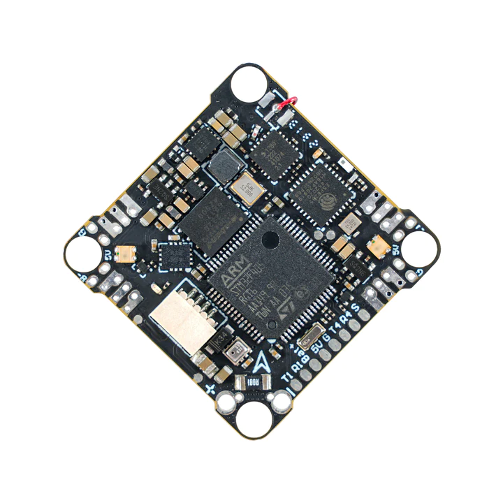
the above image and some content courtesy of BETAFPV
Note
Due to flash memory limitations, this board does not include all ArduPilot features. See Firmware Limitations for details.
Warning
this firmware only applies to the F405 variant of the autopilot.
Specifications
Processor
STM32F405RGT6 ARM (168MHz)
16MByte flash for logging
Sensors
ICM-42688P IMU (accel, gyro)
BMP-280 barometer
Voltage & 234A current sensor
Power
1S - 2S Lipo input voltage with voltage monitoring
5V, 2A BEC for internal and peripherals including air unit power
Interfaces
4 Motor outputs
SBUS input with inversion for optional use instead of internal ELRS RX
3x UARTs/serial for GPS and other peripherals, 4th UART internally tied to ELRS board
USB-C port on remote dongle
Size and Dimensions
20.5 x 20.5 mounting holes
4.68g
Where to Buy
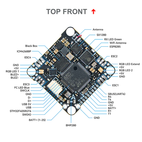
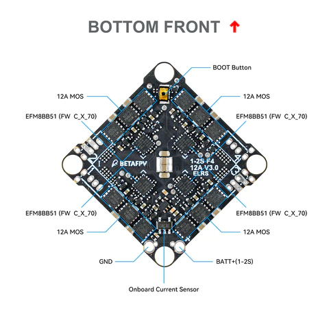
Pinout
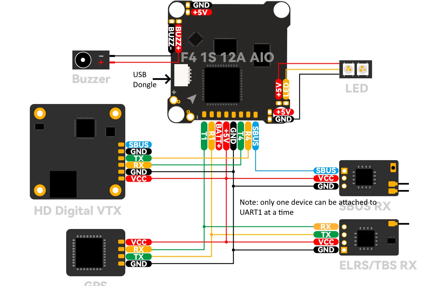
Wiring Diagram
Default UART order
The UARTs are marked Rn and Tn in the above pinouts. The Rn pin is the receive pin for UARTn. The Tn pin is the transmit pin for UARTn.
SERIAL0 -> USB
SERIAL1 -> USART1 (GPS) (DMA capable)
SERIAL3 -> UART3 (Internally connected to ELRS module)
SERIAL4 -> UART4 (DJI)
SERIAL6 -> UART6 (RX pin only USER/SBUS alternate) (via inverter from SBUS pin, DMA capable)
Serial protocols shown are defaults, but can be adjusted to personal preferences.
Servo/Motor Outputs
Internally connected to integrated 4in1 ESC with BlueJay firmware. Bi-Directional DShot capable and are configured as such by default.
RC Input
UART3 is tied internally to a 2.4GHz ELRS receiver module and defaulted to that protocol.
There is a pin provided for SBUS input also, but the SERIAL3_PROTOCOL would have to be changed to something other than “23”, and the SERIAL6_PROTOCOL set to “23”, instead.
Note
UART1 is configured by default for GPS but can be re-tasked for RC input for CRSF.etc. by changing its SERIAL1_PROTOCOL to “23”. You can also have more than one receiver in the system at a time (usually used for long range hand-offs to a remote TX). See Multiple Radio Control Receivers for details.
Any UART can be used for RC system connections in ArduPilot also, and is compatible with all protocols except PPM (SBUS requires external inversion on other UARTs). See Radio Control Systems for details.
OSD Support
The BETAFPV F4 1S 12A AIO V3 supports DJI HD air units with telemetry using UART4 RX/TX. See MSP OSD for more info.
Battery Monitor Configuration
These settings are set as defaults when the firmware is loaded (except BATT_AMP_PERVLT which needs to be changed from the default value). However, if they are ever lost, you can manually set the parameters:
Enable Battery monitor.
BATT_MONITOR =4
Then reboot.
BATT_VOLT_MULT 11.0
BATT_AMP_PERVLT 70.8
Connecting a GPS/Compass module
This board does not include a GPS so an external GPS can be connected to allow operation of position holding/tracking modes (ie LOITER,etc.).
Warning
since a compass cannot be attached, yaw information can only be determined with a GPS attached and using ArduPilot’s internal GSF yaw estimator. This yaw estimator is particularly sensitive to vibration and could result in erratic operation, or even a crash, if vibration is moderate or severe. Therefore, using positioning modes is not recommended.
Firmware
This board does not come with ArduPilot firmware pre-installed. Use instructions here to load ARduPilot the first time Loading Firmware onto boards without existing ArduPilot firmware.
Firmware for this board can be found here in sub-folders labeled “BETAFPV-F405”.